The rising incidence of infectious diseases has acted as a driving force for the accelerated development of precise, decentralized and cost-effective diagnostic technologies. Within this landscape, point-of-care (POC) devices stand out as game-changing instruments, capable of delivering quick and accurate diagnoses right at the patient’s care setting. This report outlines research undertaken by Flex’s design and engineering centers for health care, highlighting the pivotal role computational simulations play in optimizing the design of POC cassettes prior to manufacturing. The simulations not only shorten the development timeline but also enable swift adaptation to market demands.
Market Dynamics and Drivers of POC Diagnostic Technologies
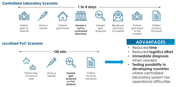
In recent years, the surging prevalence of infectious diseases[1] has created substantial demand for solutions to detect viral and bacterial load in biologic specimens in a rapid, reliable and economically sound manner.[2] Further, heightened focus on patient-centered care has propelled the market to launch advanced testing kits that are intuitive and easy to use.[3] It is in this complex scenario that point-of-care (POC) devices have taken center stage. POC devices are portable medical instruments that are easy to use and provide rapid and accurate results directly at the patient’s location without the need to transport diagnostic samples to third parties (Figure 1).
Data suggest that the global POC diagnostic market revenue is estimated to be $45 billion in 2022 and is predicted to reach $75 billion in 2027. While these estimates are illuminating, they remain hinged on current market trends, which in turn are intrinsically influenced by a myriad of unforeseeable factors.[4]
Architectural Considerations and Nuances of POC Devices
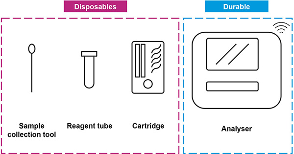
Frequently, POC devices consist of a disposable cassette, a sample collection kit and an electronic device that serves to analyze the samples via a sensing element, interface with the user and communicate data (Figure 2). The sensing element can be based on various transduction principles, such as electrochemical, optical and acoustic. The cassette can contain the necessary reagents and sample handling components for performing the diagnostic test. To allow fluid transport, it generally includes milli- or micro-fluidic pathways originating from the sample inlet, flowing through reagents along the pathway to reaction chambers where analysis takes place. Fluid movement could be induced by gravity, pneumatic pumps or capillarity. This is a fertile area for experts in computational simulations, offering myriad opportunities for fine tuning fluid dynamics, including optimizing liquid volume and preventing detrimental air bubble formations, issues often underrepresented but critically impactful.
The Role of Computational Simulations in Holistic POC Design
In the realm of computational simulations, POC devices represent a transformative platform for technological advancements. Computational Fluid Dynamics (CFD), Finite Element Analysis (FEA) and other multi-physics simulations not only shed light on the fluidic behavior but also offer invaluable insights into thermal and optical conditions. It could be a game-changer, given that such complex, multi-faceted simulations can cut down the need for physical prototyping, thereby potentially significantly reducing both manufacturing costs and time-to-market.
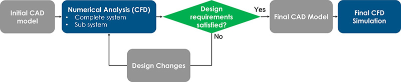
The research from Flex’s design and engineering centers for health care serves as a compelling example of this phenomenon. Here, computational simulations were deployed not merely as a preliminary step but as an integral cornerstone to the entire development process. The design constraints were meticulously outlined to encompass fluid dynamics, thermal management and environmental factors such as humidity and temperature (Figure 3). However, the keen observer will recognize that simulations, while invaluable, are only as good as the real-world data that validates them.
We analyzed a real-life example where computational simulations helped define an optimized CAD model before any physical prototypes were developed and tested, confirming the high potential of computational simulations in POC design. First, we developed an initial version of a disposable cassette (Figure 4), based on both the customer’s technical requirements and our internal subject matter expertise in fluidic devices.
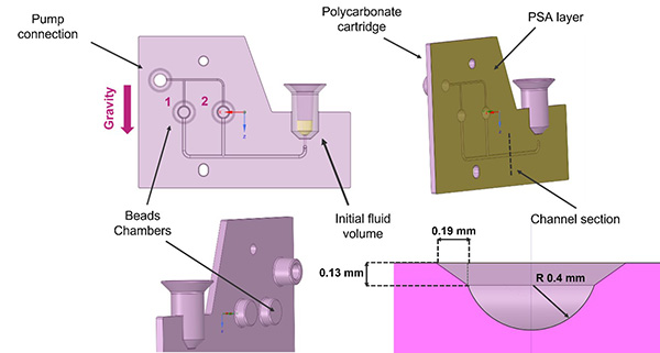
Let’s dive into the complex intricacies that define the POC cassette, a paramount entity constructed predominantly from polycarbonate, a material chosen for its unique combination of strength and transparency. The vertical architecture is initiated with an inlet chamber, precisely calibrated to capture biological samples from patients. Following this entry point, the design incorporates a millifluidic pathway that bifurcates, facilitating a well-defined spatial region, which hosts a strategically placed valve. This conduit then navigates toward a primary bifurcation, splitting into two distinct channels, each purposed to populate separate, but identically constructed, reaction chambers where the key diagnostic analyses unfold.
The millifluidic channels boast a semi-circular cross-sectional area with a radius of 0.4 mm. Hydraulic sealing is given by a Pressure-Sensitive Adhesive (PSA) layer that seamlessly adheres to the polycarbonate substrate.
To further the sophistication, we integrated specialized air channels originating from the Reaction Chambers. These channels subsequently converge, culminating at a pneumatic junction where a dedicated pump orchestrates fluid movement throughout the entirety of the cassette circuitry.
For computational simulations, we employed Flow3D software, a tool with the capabilities to simulate complex fluid dynamics. We set three core design constraints that served as non-negotiable tenets for the final cassette design:
- Ensure that Reaction Chamber 1 does not achieve full capacity prior to the filling of Reaction Chamber 2.
- Restrict the flow of liquid within the minute air channels exiting the Bead Chambers.
- Obviate fluidic instabilities such as bubble formation within the fluid pathways.
Then, we formulated some assumptions listed in Table 1:
Table 1: Physical parameters used for computational fluidic simulations.
| Fluid | Water, 20 ° |
| Physical phenomena considered | Viscosity
Surface tension effects (contact angles PSA = 115 ° and PC = 82 °) Gravity direction |
| Physical phenomena neglected | Temperature effects, reagent beads dissolving effects. |
| Environmental pressure | Atmospheric pressure. |
| Pumping pressure | P = -500 Pa |
| Simulated time | T = 3 s |
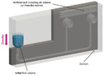
As depicted in Figure 5, the initial simulation incorporated an artificial tank to accommodate the air volume previously omitted from the computational domain. This addition was made to enforce a uniform outlet pressure boundary condition for the reaction chambers within the cassette. In the Inlet Chamber, an initial fluid volume representing the patient biological sample was positioned and inserted in the cassette by the user. Finally, we set a gravity direction pointing as depicted in the image.
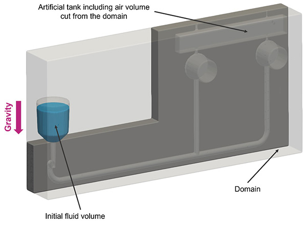
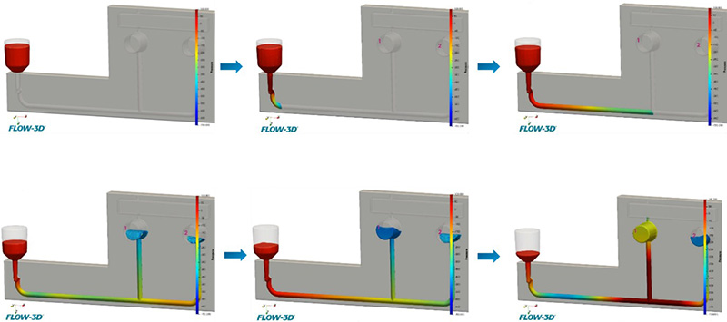
Figure 6 shows the time sequence of the results after running the simulation. In the simulated time the cassette results show almost complete perfusion by the fluid. This first run identified three criticalities to be addressed. First, an evident delay in filling of Bead Chamber 2 with respect to Bead Chamber 1, which is a deviation from the first requirement mentioned above. Following this, the computational analysis revealed that the fluid infiltrates the outlet channels at the exit of the Bead Chambers, posing a potential fluid spillage hazard from the cassette. This occurrence represents a breach of the second stipulated requirement. Finally, we observed how water exhibits an abrupt change in the filling pattern of the Bead Chambers, exposing the system to the formation of bubbles, which could impede a correct sample analysis in the Reaction Chambers.
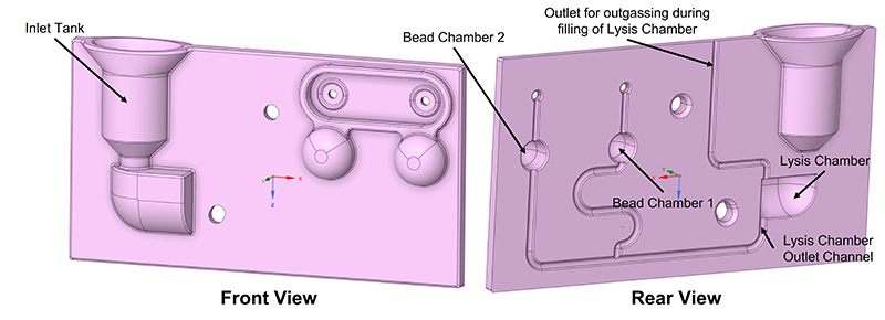
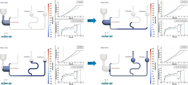
After becoming aware of the computation time, we introduced a new element, called the Lysis Chamber, commonly present in POC cassettes and dedicated to lysate, the biological components made possible by positioning the lysis reagent beads and a heater closer to the chamber, which increases chamber temperature to trigger the reaction. After adding this element, we identified three changes that can solve the criticalities mentioned above to help meet the requirements in the following simulation run. As a first counteraction, we introduced a winding of filling path to postpone fluid arrival to the Reaction Chamber 1, so that the total fluidic path length arriving to both Reaction Chambers would be identical. Next, to address the fluid entering the small size air channels, we placed vent filters in the rear of the cassette—at the top of the Reaction Chambers—that allow air to flow but not fluid. These kinds of filters need a relatively high Water Entry Pressure (WEP) to be surpassed, avoiding fluid spillage at regular working conditions. Finally, we introduced rounds in the Reaction Chambers to “smooth” out the filling profile and avoid abrupt changes in the fluid pattern. For the Lysis Chamber, we opted for an asymmetrical structural configuration, effectively addressing two critical objectives. First, it ensures continuous outgassing even as the chamber fills, accomplished by strategically increasing the distance between the Inlet Chamber and the outgassing tube. And second, this design guarantees a linear rate of chamber filling concerning time (see Figure 7).
The new fluidic design was then ready for the final simulation run, which had successfully resolved the issues identified earlier (see Figure 8 for results). In particular, we observed:
- Designed winding of fluidic path synchronizes filling of the two Reaction Chambers.
- Fluid is now confined in designed volume area, limited to Chamber 1 and Chamber 2.
- Filling pattern of Chamber 1 and Chamber 2 has been “smoothed” by introduction of rounds.
- Potential criticalities during Chamber filling have been reduced with an optimized geometry.
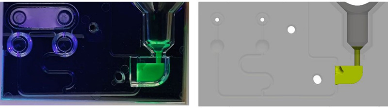
As a confirmation of the computational results obtained with Flow3D, we have developed physical polycarbonate cassettes by injection moulding-based manufacturing process to perform experimental fluidic tests. These tests were aimed to compare both the filling time of the cassette when a magnetic valve is open below the Lysis Chamber, with the time obtained computationally, and also the filling profiles of the fluid, that is the behaviour of the bubbles and the phases of filling the different compartments of the cassette over time. Two screenshots of the results are depicted in Figure 9 and Figure 10.

In conclusion, computational simulations in the design and optimization phases of point-of-care (POC) devices represents a crucial strategy to mitigate financial expenditures, saving materials and personnel resource costs, as well as speeding time to market by avoiding additional time necessary to perform some engineering tests.
Through the systematic integration of numerical analysis, complex aspects could be anticipated in the design process, leading to prototyping and manufacturing of optimized device architectures. Among the several challenges addressable by numerical simulation are: the time and profile of filling, including bubble formation, of a fluidic circuit; the determination of light path through reflective surfaces which bring light signals to a sensor; the calculation of heating time necessary to reach a certain temperature; and identification of the more stressed zone of a mechanical component that drops to the ground.
By adopting simulations as a cornerstone in the design paradigm, the innovation-to-market timeline can be remarkably reduced, facilitating rapid receptivity to emerging demands and dynamic market shifts.
References:
[1] Baker, R.E., Mahmud, A.S., Miller, I.F. et al. Infectious disease in an era of global change. Nat Rev Microbiol 20, 193–205 (2022). https://doi.org/10.1038/s41579-021-00639-z
[2] Shang, M., Guo, J., & Guo, J. (2023). Point-of-care testing of infectious diseases: Recent advances. Sensors & Diagnostics. https://doi.org/10.1039/d3sd00092c
[3] Prakashan, D., P R, R., & Gandhi, S. (2023). A systematic review on the advanced techniques of wearable point-of-care devices and their futuristic applications. Diagnostics, 13(5), 916. https://doi.org/10.3390/diagnostics13050916
[4] Point of care diagnostics market size, share, trends and revenue forecast [latest]. MarketsandMarkets. (2022). https://www.marketsandmarkets.com/Market-Reports/point-of-care-diagnostic-market-106829185.html
Related Articles
-

At Device Talks Boston in May, Ronald Kurz, Sr. Director and GM at Canon Virginia,…
-

Excess humidity can affect a pharmaceutical’s structure, chemical stability and dissolving rate, and this moisture…
-

As 3D printing gains a more prominent place in the manufacture and protoyping of medical…
-

Cybersecurity in Medical Devices: Quality System Considerations and Content of Premarket Submissions provides recommendations on…