Global market-leading original equipment manufacturers (OEMs) are facing tremendous market pressure to create innovative designs in record time for the least possible cost. In addition to maintaining the highest possible quality throughout the product’s expected lifecycle, consumers are demanding that products do more for less.
Multi-Material molding (MMM), a process whereby at least one melt processible material is bonded with at least one other material to produce a single, molded component, allows designers to optimize material properties and costs, eliminate assembly processes, and even invent ground-breaking products that could not be manufactured otherwise.
This paper will present an overview of multi-material molding – a technology that is helping manufactures meet their current market challenges – and discuss some of the design considerations involved in this approach to manufacturing.
Why use a multi-material solution?
The basic premise of multi-material molding is to take economical advantage of two or more materials with uniquely different properties by incorporating them into a single, injection molded component. A bond between the materials is achieved by mechanical, melt, chemical or any combination of these three mechanisms:
Mechanical lock – The softer material encapsulates or flows into holes and undercuts in the rigid component before solidifying and providing the connection between the two materials. With proper design a mechanical lock can provide very high bond strength. It also provides the greatest latitude in the selection of the overmold material.
Melt and/or chemical adhesion – The bond may be derived entirely from melt and/or chemical adhesion between the surfaces of the two components. The former requires both a close match in melting points and some similarity in chemical properties wherein the two materials melt together at the interface and form a bond. The latter depends exclusively on a very close chemical compatibility. A chemical reaction occurs at the material interface to form the bond.
Single-material vs. multi-material designs offer the following advantages:
- Leverages the physical or chemical property benefits of multiple materials;
- Enhances fit, sealing, ergonomic, and other product performance characteristics from dissimilar materials – especially functional soft/rigid combinations;
- Improves product integrity, reliability, and safety;
- Allows for unique aesthetics and incorporation of information like color coding, branding, bar coding, permanent labeling; and
- Expands design space for unique designs.
Assembly vs. Multi-Material Molding offers:
- Improved physical and mechanical performance;
- Cost and weight reduction;
- Fewer assembly steps and components;
- Improved quality, consistency, and longevity; and
- Ergonomic benefits like soft-touch.

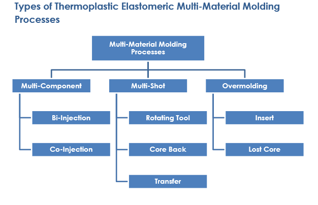
Multi-component injection molding involves either simultaneous or sequential injection of two different materials through the same or different gate locations in a single mold. In the co-injection process, both materials are injected simultaneously into the same tool, and the softer material migrates to the outer layer. Material compatibility is critical to this process and must be carefully controlled.
Multi-shot injection molding involves injecting different materials into the mold in a specified sequence where the mold cavity geometry may change between sequences. The process most often requires specialized equipment and tooling.
Overmolding involves molding a resin around a previously-made substrate. Most often used for molding softer thermoplastic elastomers onto rigid plastics, overmolding requires the least hardware reconfiguration and investment of all multimaterial molding process. To achieve a chemical or adhesive bond, the overmolded resin must be sufficiently hot to melt the surface of the rigid substrate or it must activate that surface to achieve a chemical bond. When a non-elastomeric product is completely overmolded, this process is referred to as fully-encapsulated insert-molding.

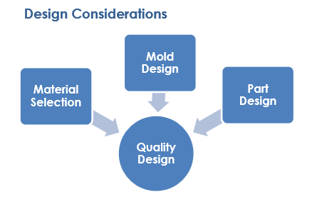
Material Selection
The first step in material selection requires making a list of the minimum and desired performance characteristics required from both the rigid substrate and the softer materials. These two lists can then be merged to select a compatible pair of materials to achieve all of the requirements and most of the desired properties. Choosing compatible materials is critical to ensuring a good bond. The melt temperature range two materials should be in the same range to enhance bonding. If the melt temperature of the outer material is too low to melt the surface of the substrate, the bond can be weak. However, if the melt temperature is too high, the substrate might soften and distort.
Mold design
Mold surface finish – Unless high gloss is desired, cavity surfaces should be slightly textured or matte finished to minimize the appearance of flow lines and improve ease of demolding. Most TPE-type materials tend to stick to mold surfaces. Texture minimizes injection molding flaws and enhances the feel of the part so that the part feels softer to touch than the durometer actually measures.
Runners and sprues – Streamlined designs using a full round or trapezoidal runner should be used whenever possible to minimize melt turbulence, pressure drops, and sticking. A draft of 3-5° and smooth, but not polished, surfaces will help improve flow and facilitate automatic part removal.
Gates – In general, pin gates and/or subgates are used; film gates are employed along the edges of rectangular, flat parts. The flow-length-to-wall-thickness ratio is critical for adhesion. A good practice is to start with small gates relative to mold volume. Gates can be opened up after an initial sampling.
Venting – Venting provides a path for the air to escape from the cavity as the injected melt displaces it. Additionally, air entrapment is a big problem for bonding, and It generally results in poor adhesion and short shots at the end-of-fill locations.
Part ejection – When pin ejectors are used, they should have a large surface area and act on the thickest sections of the part to minimize marking of the surface. When a molded part must have very little or no draft, stripper plates are recommended for ejection.
Mold Temperature – Mold temperature is critical to insure that the cycle time is optimized, the parts achieve the designed shrinkage, and parts can be easily removed. Individual mold temperature control units for each side of the tool are recommended.
Shutoff – A good shutoff design features a sharp transition between the overmold and substrate. A gradual thinning, or feathering, will result in a poor bond between materials with gradual delamination and failure.
Part design
Thermal Shrinkage – The degree of shrinkage for injection molded parts can be affected by molding parameters and part geometry. Normally, the shrinkage factor of first shot material determines the rest of the components shrinkage coefficient.
Uniform Wall Thickness – It is necessary to maintain a uniform wall thickness in the areas of the substrate that will be filled or covered by the second shot. Thin and uniform section thickness should be used so that the entire part can cool down rapidly at the same rate. Thick sections take a longer time to cool than thin sections resulting in the presence of internal stress in the portions of the part where the wall thickness changes. These residual, internal stresses can lead to warpages and reduced service performances.
Corner Flow – Generous corner radii are required to prevent thin inside corners. Fillets should be created and corners should be rounded so that the molten plastic flows smoothly to all the portions of the part.
Shutoff Areas & Style Lines – It is often necessary to provide cosmetic “style” lines between the substrate and the overmolded part along the shutoff (boundary) areas on the substrate where there is slight deformation. This aesthetic issue can be avoided by creating an intentional area, such as a groove, to hide this transition. This groove can act as a convenient place for creating a mechanical attachment area between the two materials.
Overmold Support – The substrate must be designed so that the 2nd shot mold can adequately support the areas being molded. Features under the 2nd shot such as ribbing, should be kept to a minimum.
Draft Angles – Draft angles need to be imparted to vertical or near-vertical walls for ease of removal of the part from the mold assembly. Drafting also reduces tool and part wear considerably. Typically, the required draft angle ranges from a fraction of a degree to several degrees.
Application areas
A wide range of molded medical, automotive, and industrial/consumer goods employ overmolded designs that combine the structural strength of rigid plastics with the aesthetics, warm feel, sure grip, abuse resistance, and durability of a thermoplastic elastomer. Such applications range from toothbrushes, which need last only a few months, to grips on construction-quality power tools, which are expected to last for years under very severe conditions, to implantable medical devices, which may be in contact with various fluids, acids, and lipids indefinitely and must be designed to last for the life of the patient.
Conclusions
Multi-material molding technology is helping manufactures meet their current market challenges by allowing designers to optimize material properties and costs, eliminate assembly processes, and even invent ground-breaking products that could not be manufactured otherwise.


